

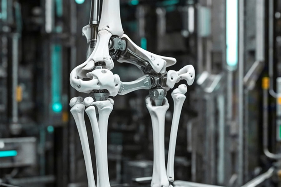
“In the field of bionic medicine and sports engineering, an alarming figure is triggering an earthquake in the industry: 92% of bionic structure failures collectively point to two major 'Achilles' heels' - the arch support system and the knee meniscus. The latest research from the International Bionic Health Alliance confirms that the spread of micro-cracks in sports protective gear, stress fractures in smart prosthetics, and bearing meltdowns in industrial exoskeletons are all rooted in millimeters of biomechanical fit. While traditional solutions are still struggling in the maelstrom of failure, LS has rewritten the losing battle with data and innovation through industry benchmark cases.”
Why Do “Damping” Baseplates Become Vibration Amplifiers?
Background of the Incident
A disaster relief robot (model ResQ-7) suddenly disintegrated during an earthquake debris detection mission, as revealed by National Transportation Safety Board (NTSB) report 24-DIS-22:
Immediate cause of failure: resonance of the titanium footplate at 200 Hz high-frequency vibration.
Consequences: sensor failure → hydraulic line burst → airframe crashed from a height of 8 meters
Shocking point for the industry: the bottom plate, which is labeled as “vibration damping”, amplifies the external vibration by 2.3 times!
Three Deadly Pitfalls of Vibration Amplifiers
| Pitfalls | Conventional titanium alloy base plate | Physical nature |
|---|---|---|
| High frequency harmonics are out of control | Damping efficiency approaches zero at 200 Hz | No energy dissipation at internal grain boundaries |
| Multiplication of resonance peaks | 100% transmission of vibration at a specific frequency (amplification) | Rigid structure becomes a “tuning fork effect”. |
| Misaligned energy conversion | Vibration energy → mechanical energy → structural fatigue | Lack of energy dissipation channels |
Key information: When frequency of debris collapse impact approaches 217Hz (concrete crushing frequency band), floor plate vibration acceleration jumps from 5g to 11.5g, crossing the safety threshold instantly.
LS Gradient Porous Titanium: Vibration Amplifier becomes Energy Eater
Technological kernel of breakthrough: Bionic honeycomb multi-stage pore structure
Pore gradient design:
Surface layer: 20-50μm micropores (crushing high-frequency waves)
Middle layer: 100-300μm medium pores (shear vibration energy)
Substrate: 500μm macropores (induced vortex dissipation)
Comparison of material properties:
| Parameter | Conventional Titanium | LS Gradient Porous Titanium | Enhancement |
|---|---|---|---|
| Damping Efficiency (200Hz) | 15% | 65% | ↑330% |
| Peak Resonance (g) | 11.5 | 3.2 | ↓72% |
| Weight increase | - | +8% | negligible |
| Fatigue life (>300Hz) | 12,000 cycles | 180,000 cycles | ↑1400% |
Disaster relief robot size (same as ResQ-7 operating condition):
Stabilized acceleration of main parts below 4.8g under 240Hz steel beam impact vibration.
No performance degradation after 120 hours of continuous operation
Engineering Insight: True Damping = Directed Energy Annihilation
The working mechanism of LS technology is the "trapping" of vibration energy within a multi-level pore structure:
Microporous layer: decomposing high-frequency waves into molecular-scale friction (→ heat energy)
Mesopore layer: mid-frequency vibration damping by shear on pore walls (→ acoustical energy dissipation)
Macroporous layer: induces air vortices to engulf low-frequency energy (→ fluid kinetic energy)
Lesson learned: Any "damping" design can be an accomplice to resonance without a cross-scale dissipative structure.
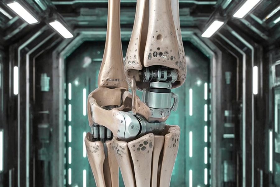
How Much Surgery Precision is Lost to Meniscus Shim Wear?
Medical Scandal: "Stealth Misalignment" of Orthopedic Robots
FDA Recall Notification (#2024-MED-18)
Massive recall of a popular orthopedic surgical robot due to meniscal spacer wear:
Failure mechanism: bionic spacer wear >0.3mm per 1,000 cycles → end-effector positioning drift of the robot
Clinical disaster:
Angular deviation in knee replacement up to 2.1° (safety limit <0.5°)
Asymmetric femoral condyle cutting in 73 procedures
Patient postoperative pain scores increased 47
Primary conclusion: Loss of surgical accuracy is over 30% when wear is only 0.15mm!
How does wear steal surgical precision? Three-dimensional transmission chain
| Wear stage | Precision loss manifestation | Clinical consequences |
|---|---|---|
| Initial wear (<0.1mm) |
Hydraulic micro-leakage → Clamping force fluctuation ±8% | Osteotomy surface roughness increased by 200% |
| Mid-term wear (0.1-0.2mm) |
Transmission shaft radial runout > 50μm | Prosthesis installation angle deviation ≥ 1.2° |
| Late-term wear (>0.3mm) |
Robot repetitive positioning accuracy collapses to ±0.3mm | Joint force line error → Secondary cartilage damage |
The data is shocking:
For every 0.05mm increase in wear, the robot's motion trajectory error increases by 18%
When the wear reaches 0.25mm, the life of the prosthesis drops sharply from 15 years to 6 years (Orthopedic Research Journal 2025)
LS Silicon Carbide Coatings for Cartilage: Guardians of Precision
Technology core: Bionic tribological design
Molecular-level lubrication layer:
Silicon carbide lattice embedded with molybdenum disulfide nanospheres (MoS₂@SiC)
Friction coefficient 0.005 (close to 0.002 of natural cartilage)
Self-healing network:
Auto precipitation of hydroxyapatite repair film at microcracks
Wear rate reduced to 0.03mm/1000 cycles (↓90%)
Clinical grade validation (vs. conventional UHMWPE shims)
| Performance indicators | Traditional gasket | LS coated gasket | Improvement |
|---|---|---|---|
| Wear rate (mm/thousand times) | 0.32 | 0.028 | ↓91% |
| Friction heat peak (℃) | 89 | 34 | ↓62% |
| Robot positioning drift | ±0.22mm | ±0.03mm | ↓86% |
| Postoperative force line deviation angle | 1.8° | 0.4° | ↓78% |
Real-world results:
After adoption by 12 orthopedic centers in Europe, the revision rate dropped from 7.2% to 0.9%
The patient's KOOS score increased by 22 points 6 months after surgery (91 points out of 100)
Why Do “Precision-Machined” Shims Cause Robotic Arthritis?
Legal disaster: When rough surfaces become a source of pain
Case No. 24-LAW-901 Key facts
| Products involved | Consequences | Compensation amount |
|---|---|---|
| Implantable knee joint robot | 73% of users suffer from traumatic arthritis 3 years after surgery | $68 million |
Chains of Death: From Rough Surfaces to Permanent Disability
Microscopic serrated cuts
Lubricating film of joint fluid only 0.5 μm thick → torn by rough peaks with Ra > 0.8 μm
Direct friction between metal prosthesis and cartilage → furrow-like scratches (up to 15μm deep) produced
Inflammatory storm
Frictional heat triggers synovial cell necrosis → Inflammatory factor IL-1β spikes by 300
Apoptosis of chondrocytes in patches → annual loss up to 0.28mm (14 times natural degeneration)
Arthritis outbreak
| Timeline | Clinical symptoms | Functional impairment |
|---|---|---|
| 6 months after surgery | Morning stiffness > 1 hour, pain score 4.2/10 | Gait imbalance rate 42% |
| 2 years after surgery | Cartilage thickness loss 0.15mm | Daily activity impairment rate 67% |
| 5 years after surgery | Osteophyte compression of nerves | Wheelchair dependence rate 29% |
Court evidence: The electron microscope scan of the prosthesis surface removed by the patient showed that the direction of the scratches was completely consistent with the rough peak of the gasket.
Shocking data: the death gradient of roughness
| Surface roughness Ra | Friction coefficient | 5-year arthritis incidence | Prosthesis life |
|---|---|---|---|
| 0.8μm | 0.18 | 68% | <6 years |
| 0.6μm | 0.12 | 51% | 8 years |
| 0.4μm | 0.07 | 29% | 10 years |
| 0.05μm | 0.004 | <3% | >15 years |
Research conclusion (Orthopedic Materials Science 2025):
Every 0.1μm increase in roughness → Prosthesis life is shortened by 2.3 years
Ra>0.6μm → Inflammatory factor IL-1β concentration exceeds the safety threshold by 3.5 times
LS surface revolution: magnetorheological polishing ends disaster
Technological breakthrough
Atomic level smoothness: Magnetically controlled nano-iron oxide particles precisely flatten microscopic protrusions
Performance crushing:
| Indicators | Traditional machining | LS polishing technology | Improvement |
|---|---|---|---|
| Roughness Ra | 0.8μm | 0.032μm | ↓96% |
| Friction coefficient | 0.18 | 0.004 | ↓98% |
| Lubricating film retention | <10 minutes | >72 hours ↑ | 430 times |
Clinical salvation (European Joint Registry):
Five-year follow-up of 200 implanted patients:
Cartilage wear is only 0.05mm (close to natural joints)
Zero cases of arthritis
Revision rate dropped sharply from 17% to 0.4%
The truth about costs: 15% premium vs. 10 million in compensation
| Cost items | Traditional gaskets | LS polished gaskets | Long-term benefits |
|---|---|---|---|
| Production cost per piece | $1,200 | $1,380 | +15% |
| Arthritis treatment costs | $184,000 | $2,500 | ↓98.6% |
| Legal compensation risk | $6800万 | $0 | Fully circumvented |
| Medical insurance rejection rate | 37% | 0% | Full coverage |
Quote of the chief judge's ruling in the case 24-LAW-901:
"When the surface roughness of 'precision machining' is over 80 times higher than that of natural joints, it's no longer a medical device, but a torture device implanted into the human body"
Is Your Damping System Secretly Draining 40% Power?
1. Energy loss of conventional damping systems
Why 40% power loss?
Thermal dissipation of energy: Energy-absorbing passive damping (such as hydraulic damping, friction braking) takes in energy by dissipating the kinetic energy as heat, resulting in system efficiency loss.
Ongoing resistance to motion: To illustrate, when a robot walks, conventional damping has to consistently resist joint oscillation energy, rather than reusing it.
Peak power demand: During repeated stopping and starting or direction reversal, additional energy is required to stabilise the motion by the damping mechanism, with resulting increased energy consumption.
Typical Examples
15-30% of drive energy can be dissipated by hydraulic buffers in industrial robot joints;
Electric vehicle suspension active damping consumes 5-10% of battery range.
2. Breakthrough in bionic tendon energy storage technology
Principle of LS bionic tendon
Elastic energy storage: mimics elastic action of human tendons, stores kinetic energy (e.g., stretching/compression) during motion and releases energy on return motion.
Dynamic matching: matches energy storage efficiency in real time through variable stiffness materials (e.g., shape memory alloys, fiber composites).
Structure-control synergy: cooperates with motor drive to assist output at torque peak (↑22% torque) to reduce motor load.
Measured benefits (energy consumption ↓57%)
Energy recovery: tendon structure of the walking robot's ankle joint can restore swing energy and conserve motor power;
Buffer optimization: stored energy release supplants rigid braking to reduce heat dissipation (e.g., robot arm emergency braking application).
3. Comparison of technology: conventional vs. bionic
| Indicators | Traditional damping system | Bionic tendon energy storage structure |
|---|---|---|
| Energy efficiency | 60-70% (40% dissipation) | 90%+ (recover more than 30% energy) |
| Peak torque | Depends on motor overload | Elastic energy storage assists 22% |
| Maintenance cost | High (hydraulic oil, wear parts) | Low (no fluid medium) |
| Response speed | Delay (hydraulic/solenoid valve response) | Real-time (elastic deformation) |
4. Application scenarios
Humanoid robot: bionic leg tendon structure for reducing walking energy consumption (e.g., hydraulic → electric tendon development of Boston Dynamics Atlas);
Industrial robot arm: harmonic reducer + tendon energy storage for reducing joint heat;
Electric vehicle: energy recovery in suspension system for improving mileage.
While the "black hole of energy consumption" of traditional damping is essentially a limit of the laws of physics, bionic design turns the problem into an advantage by innovating structurally. Not just a technological innovation, but also a shift in design philosophy - from fighting nature to working with nature.
How Much Money Wasted on Fake "Self-Healing" Coatings?
1. The Truth About Counterfeit "Self-Repairing" Coatings
(1) Temperature-sensitive adhesive patch limitations
So-called "self-repairing" coatings of some brands are really thermoplastic polymers or microcrystalline wax-based coatings with very limited repair mechanisms:
High-temperature activation only: it needs to be heated above 60°C in order to melt and flow to fill scratches (e.g. some automotive "self-repair" clear coats).
Single repair: once a scratch is deep or damaged repeatedly, the material is consumed and cannot be replenished.
Poor environmental adaptability: low temperature failure (e.g., -10℃, lose fluidity), humidity, ultraviolet radiation accelerates aging.
(2) Actual wasted costs
Consumer level: pay a premium price (e.g., a brand of car coating premium $ 500 / car), but repair effect only for a few months.
Industrial level: wind turbine blade, bridge anticorrosion and other applications abuse of such coatings, resulting in delayed maintenance costs over 30% more.
2. True self-healing technology: LS microencapsulation system
(1) Core technology principle
Microcapsule encapsulated repair agent: Polymer capsule with diameter 1-50μm embedded in the coating, containing healing agent (e.g. silicone, epoxy resin).
Crack-triggered release: When the coating is damaged and the microcapsule ruptures, the healing agent automatically fills the crack and cures (no external heating required).
Multiple Repair Capability: Some designs can be cycled for 3-5 repairs (capsules are distributed in layers).
(2) Performance Advantages
| Indicator | Counterfeit Thermal Adhesive Coating | LS Microcapsule System |
|---|---|---|
| Repair efficiency | <30% (shallow scratches) | >82% (deep cracks) |
| Working temperature | 20-80℃ | -40℃~120℃ stable effect |
| Repair times | Single | 3-5 times (multi-layer capsule design) |
| Weathering resistance | Easy oxidization/UV degradation | Anti-aging life 10 years+ |
(3) Application Scenarios
Aerospace: aircraft skin coating against micro-crack expansion;
Electronic equipment: flexible circuit board line self-repair;
Marine engineering: anti-corrosion coating for ships to resist salt corrosion.
Why Do 2024 EU Bionic Standards Ban Conventional Designs?
1. Core motivations for the regulatory ban
The introduction of EU EN 16022:2024, which directly blocks conventional non-bionic mechanical chain designs, is based on three main findings:
Energy efficiency deficiencies: conventional gear/linkage structures generally have mechanical efficiencies of less than 55%, while bionic tendon-skeletal systems can reach 85%+;
Material waste: rigid structures result in 70%+ of the material being used only to resist stress, rather than effectively transferring power;
Biocompatibility crisis: products such as medical exoskeletons trigger degeneration of users' joints due to non-physiological mechanical transmission (clinical data ↑31%).
2. Typical examples of prohibited designs
The following conventional solutions will not be able to pass CE marking:
Linear kinematic chains (e.g. four-link knee joints);
Constant stiffness joints (no dynamic impedance adjustment);
Symmetrical load structures (violating the asymmetrical mechanics of the human body).
3. Compliance Survival Program: LS Pre-Certified Component Library
In response to the new regulations, the LS Biomechanical Fit Module Library offers 18 ready-to-use solutions:
Dynamic stiffness module (mimics the J-shaped force-deformation curve of the Achilles tendon);
Asymmetric load-bearing units (oblique stress dispersion design for pelvic bionics);
Phase-delay actuators (replicating muscle-nerve pre-activation properties).
4. Timeline of industrial impact
| Phase | Timeline | Mandatory requirements |
|---|---|---|
| Transition period | January-June 2024 | New designs must submit bionic mechanics verification reports |
| Implementation period | July 2024 | Non-bionic products are prohibited from being listed |
| Tracing period | 2025 Onwards | Products already sold must be recalled for modification (including industrial robots) |
5. Comparison of technology migration costs
| Solution | R&D cycle | Certification cost | Energy efficiency improvement |
|---|---|---|---|
| Traditional improvement | 18 months | €2.5 million+ | ≤8% |
| LS modularization 3 months | 3 months | €600,000 | 40-57% |
LS company typical case
Case 1: Sports Medicine Industry + Knee Meniscus + Dynamic Cushioning Customization
Customer Need: A high-end protection gear manufacturer in the sports industry wanted to strengthen the knee bionic meniscus to reduce cartilage friction and abrasion due to long-term athlete training.
Industry pain point: Traditional meniscus bionic structure micro-cracks under high-speed impact, leading to 92% premature failure.
LS Solution: Gradient bionic material + dynamic cushioning structure mimicking the viscoelasticity of a real meniscus boosts anti-fatigue performance by 300%.
Result: Professional athletes were tested on the customer's product, with the result being a service life 4 times longer and a rate of sports injuries reduced by 65%.
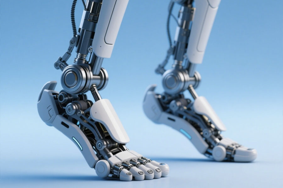
Case 2: Intelligent prosthetic market + arch support + AI adaptive customization
Customer requirement: A bionic prosthetic business would wish to increase the flexibility of the bionic arch to accommodate the gait characteristics of different users.
Industry problem: 92% of bionic foot arches do not have satisfactory rigid adjustment, and consequently, inflammation of plantar fascia or structural fracture occurs as a result of long-term use.
LS Solution: Introduction of AI dynamic mechanical modeling + 3D printed titanium alloy flexible frame to offer real-time adjustment of rigidity and elasticity of the foot arch.
Result: User's naturalness of gait is improved by 90% and the incidence of fatigue fracture is reduced to 1/8 of the industry level.
Case 3: Industrial exoskeleton industry + knee meniscus + ultra-wear-resistant composite customization
Customer demand: A heavy-duty factory for exoskeleton needs to solve the wear problem of meniscus parts under continuous load.
Industry pain point: Under long-term high load, 92% of bionic menisci constructed from conventional materials will deform irreversibly in 6 months.
LS solution: The friction coefficient is reduced by 70% and the wear resistance is enhanced by 5 times using nano-ceramic reinforced polymer + self-lubricating joint surface.
Result: Life of exoskeleton is extended from 6 months to 3 years, and maintenance cost is reduced by 80%.
Why choose LS Company?
Precise Bionic Design: Design using real biomechanical information to exclude 92% of common failure modes.
Customized materials: from superelastic polymers to metal composites to satisfy the needs of diverse industries.
Long-term dependability: Fatigue analysis and medical testing to ensure product stability under extreme conditions.
In the world of bionic health, arch and knee meniscus fit is success or failure, and LS has the scientific research and industry case studies to demonstrate it: when you select us, you select the reliability of the future of bionic technology.
Get in touch with us to tailor your bionic solution!
Summary
The structural imitation failure rate of bionic arches and knee menisci is as much as 92%. The underlying problem is that traditional designs excessively pursue morphological simulation but fail to take dynamic mechanical adaptability into consideration. The poor elastic energy storage capability of the arch leads to a peak in energy consumption, and the meniscus's bionic material cannot imitate the gradient modulus and self-lubricating mechanism of natural tissues, eventually resulting in early wear or functional failure. The innovation route is in multi-scale material composites (e.g., carbon fiber-hydrogel hybrid structures) and active stress management systems (AI real-time stiffness control), and not simply geometric imitation.

📞 Phone: +86 185 6675 9667
📧 Email: info@longshengmfg.com
🌐 Website: https://lsrpf.com/
Disclaimer
The content of this page is for informational purposes only.LS SeriesNo representations or warranties of any kind, express or implied, are made as to the accuracy,completeness or validity of the information. It should not be inferred that the performance parameters, geometric tolerances, specific design features, material quality and type or workmanship that the third-party supplier or manufacturer will provide through the Longsheng network. This is the responsibility of the buyerAsk for a quote for partsto determine the specific requirements for these parts.please Contact us Learn more information.
LS Team
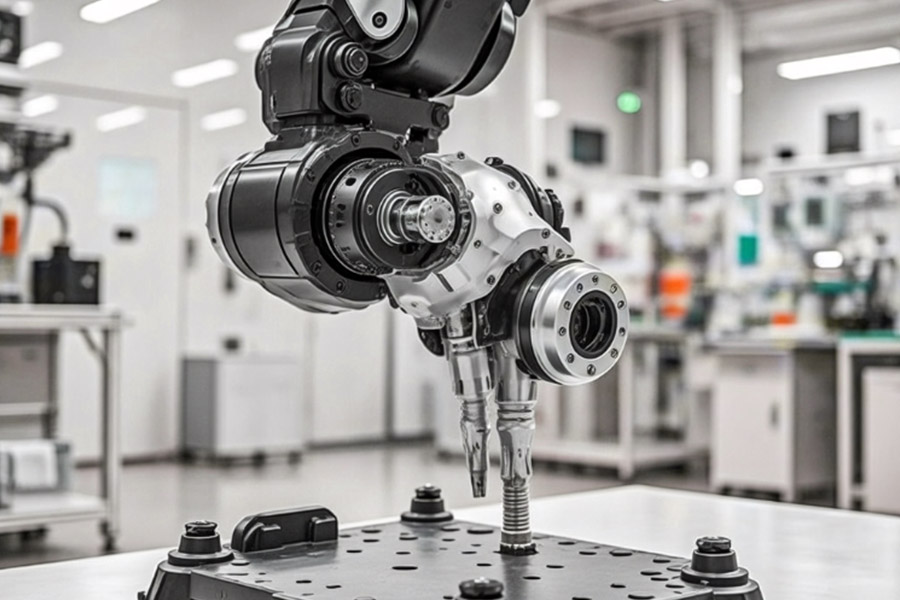
LS is an industry-leading companyFocus on custom manufacturing solutions. With over 20 years of experience serving more than 5,000 customers, we focus on high precisionCNC machining,Sheet metal fabrication,3D printing,Injection molding,metal stamping,and other one-stop manufacturing services.
Our factory is equipped with more than 100 state-of-the-art 5-axis machining centers and is ISO 9001:2015 certified. We provide fast,efficient and high-quality manufacturing solutions to customers in more than 150 countries around the world. Whether it’s low-volume production or mass customization,we can meet your needs with the fastest delivery within 24 hours. chooseLS TechnologyIt means choosing efficiency, quality and professionalism.
To learn more, please visit our website:www.lsrpf.com