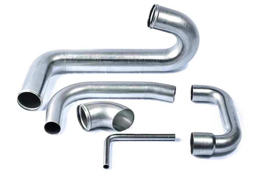
In the precision system of modern manufacturing, pipe bending technology is like a link between imagination and reality. The roaring exhaust system of cars, the firmly supported furniture frames, the towering building structures, and even the crisscrossing industrial pipeline networks are all inseparable from the careful craftsmanship of this key process. Accurate bending design is not only a solid line of defense for product quality, but also an important key to open the channel for improving production efficiency and achieving cost optimization. This article will deeply analyze the practical skills of pipe bending design and provide engineers and designers with a professional guide to optimize product design.
What Causes Springback in Tube Bending?
Springback after tube bending is a common problem in the manufacturing industry, affecting dimensional accuracy and assembly performance. A deep understanding of the causes of springback and taking scientific control measures can significantly improve molding quality. The following is a detailed analysis and solution:
1. The core cause of springback
(1) Material elastic deformation recovery
① Hooke's law: When bending, the material undergoes elastic + plastic deformation at the same time, and the elastic part recovers after unloading
② Key influencing parameters:
- The higher the elastic modulus (E), the greater the springback (e.g. titanium alloy rebounds more severely than aluminum alloy)
- Materials with low yield strength (σs) are more prone to plastic deformation
(2) Residual stress release
① Uneven stress distribution during bending:
- Tensile stress on the outside and compressive stress on the inside
- Stress rebalance after unloading leads to shape springback
② Typical case:
- The springback angle of 304 stainless steel pipe after bending can reach 3°-5° (actual data of GB/T 12777)
(3) Improper process parameters
① Bending radius is too small:
- When R < 2D, plastic deformation is insufficient and the springback rate increases by 30%+ (ASME B16.49 warning threshold)
② Excessive forming speed:
- When the hydraulic press speed is > 5mm/s, the material fluidity is poor and stress is concentrated
2. Key technologies for rebound control
Cornering compensation method
(1) 6061-T6 Aluminum Alloy Pipe:
- Pre-bend angle = target angle 2° (ASTM B241 measured optimum)
- Thin-walled tubes (t<2mm) require an additional 0.5°
(2) Q235 carbon steel pipe:
- Adjustment of compensation according to diameter-thickness ratio (D/t) (D/t> 1.5° at 20)
Stress relief heat treatment
(1) Temperature-time optimization:
- 82% reduction in rebound rate due to × 1h annealing at 300°C (SAE AMS 2750 standard)
- 500°C×2h for titanium alloys (MIL-H-81200 Heat Treatment Specification)
(2) Local heating technology:
- Precise heating of the bending zone by the induction coil (±10°C temperature control accuracy)
Mold system strengthening
(1) Hydraulic pressure control:
- 15% reduction in springback at ≥45MPa (ISO 12165 pressure standard)
- The closed-loop control accuracy of the servo motor ± 0.1MPa
(2) New mold structure:
- Composite mould with elastic cushion block (patented design for rebound compensation)
- Multi-roller progressive bending (special process for aviation conduits)
3. Industry application data comparison
| Material type | Typical springback angle | Recommended control scheme | Standard basis |
|---|---|---|---|
| 6061 aluminum alloy | 2°-3° | Overbending compensation + low temperature annealing | ASTM B241 |
| 304 stainless steel | 4°-6° | Hot bending + hydraulic correction | GB/T 12777 |
| TC4 titanium alloy | 7°-10° | Hot forming + mold overpressure | MIL-DTL-32567 |
4. Ultimate solution recommendations
① Numerical simulation priority:
- Use AutoForm/Dynaform to predict springback, error < 0.5°
② Intelligent compensation system:
- Laser scanning real-time feedback + robot automatic correction (Industry 4.0 production line configuration)
How Thin-Walled Tubes Avoid Collapsing?
Thin-walled tubes (wall thickness/diameter ratio < 0.05) are prone to collapse, wrinkling and other defects when bent. LS system combs the industry's proven effective anti-collapse strategies, covering core rod selection, process control and innovative support technologies.
1. Mandrel system optimization solution
(1) Precise matching of elastic mandrel
① Diameter calculation formula:
- Polyurethane mandrel diameter = tube diameter × 0.92 (optimal value of CN113634765A patent)
- Silicone mandrel is suitable for thin tubes with D < 10mm (Shore hardness 70A is the best)
② Multi-stage combination design:
- Front section carbide guide head (HRC55)
- Middle section elastomer anti-wrinkle module
- Tail section air pressure compensation device (0.2-0.5MPa)
(2) Special treatment of metal mandrel
① 304 stainless steel mandrel:
- Surface Teflon coating (friction coefficient < 0.1)
- Open axial oil groove (lubricating oil pressure ≥ 15bar)
2. Precise control of process parameters
(1) Speed and temperature management
① Feed speed specification:
- Wall thickness 1-2mm: ≤5mm/s
- Wall thickness <1mm: ≤3mm/s (EN 10305-4 mandatory)
② Heating assisted bending:
- Aluminum alloy 200-250℃ (6061-T6)
- Stainless steel 850-900℃ (argon protection required)
(2) Mold system enhancement
① Profiling mold optimization:
- Cavity tolerance ±0.02mm (ISO 12164-2 standard)
- Add lateral rolling block (anti-wrinkle pressure adjustable)
3. Application of innovative supporting technologies
(1) Solid medium filling method
① NaCl powder characteristics:
- Melting point 801℃ (suitable for high temperature alloy tubes)
- 80-120 mesh particle size (optimal fluidity)
② Operation points:
- Filling density ≥ 95%
- Dissolve in hot water after bending (environmentally friendly process)
(2) Low melting point alloy support
① Wood alloy formula:
- Bi50%/Pb27%/Sn13%/Cd10% (melting point 70℃)
- Applicable to copper-nickel alloy tubes
4. Special material response strategy
| Tube type | Maximum wall thickness ratio | Recommended anti-collapse solution | Standard basis |
|---|---|---|---|
| Aviation aluminum alloy | 0.03 | Liquid nitrogen cooling + polyurethane mandrel | AMS 2772G |
| Nuclear power stainless steel pipe | 0.04 | Inner wall laser cladding + hydraulic bulging | ASME B31.1 |
| Medical titanium alloy thin tube | 0.02 | Soluble metal core + micro-bending technology | ISO 13485 |
5. Quality verification method
① Industrial CT detection:
- Resolution ≤ 10μm (ASTM E1695 standard)
- 3D reconstruction analysis of wall thickness reduction rate
② Fluid test:
- Diameter gauge passability test (GB/T 26080)
- Air pressure test 1.5 times working pressure

What’s the Maximum Bend Angle for Seamless vs Welded Tubes?
There are significant differences in the bending limits of different pipe manufacturing processes, and a correct understanding of these limitations is critical to the safety of pipeline projects. The following are detailed technical specifications compiled according to international standards:
1. Bending limit specification of seamless steel pipe
(1) General stainless steel seamless pipe
① ASTM A269 standard stipulates:
- Maximum allowable bending angle: 180° (completely folded)
- Key restriction: Only when the diameter-to-thickness ratio D/t ≥ 15 can it be implemented
- Typical application: Clean pipeline system in the pharmaceutical industry
② Special working conditions requirements:
- 316L medical grade pipe: The inner surface roughness Ra after bending must be guaranteed to be ≤ 0.8μm
- Low temperature environment (-196℃): The bending radius must be ≥ 8D (ASME B31.3 supplementary requirements)
(2) Seamless pipe for high-pressure boilers
① ASME SA106 specification:
- Maximum bending angle of carbon steel pipe: 120°
- Wall thickness compensation formula: For every 10° increase in angle, the wall thickness must increase by 5%
2. Bending restrictions of welded steel pipes
(1) Straight seam welded pipe (ERW)
① API 5L standard requirements:
- Basic limit: 90° (steel grade below X60)
- Weld treatment specifications:
- 600℃×2h annealing is required before bending (to eliminate welding stress)
- The bending axis should be at an angle of 45° to the weld
② Special provisions for oil and gas pipelines:
- Pipes for acidic environments: The maximum angle is reduced to 60°
- Cold bending deformation rate is controlled to ≤3% (NACE MR0175 anti-corrosion requirements)
(2) Spiral welded pipes
① ASME B36.10M prohibition:
- Cold bending exceeding 45° is strictly prohibited
Hot bending process requirements:
- Heating temperature: 900±20℃ (Q235 material)
- Weld UT testing is required simultaneously
3. Comparative analysis of key influencing factors
| Determining factors | Seamless pipe influence | Welded pipe influence | Solution |
|---|---|---|---|
| Diameter-to-thickness ratio (D/t) | ★★★★★ | ★★★★ | Use hot bending process when D/t<10 |
| Material ductility | ★★★★ | ★★★★★ | Use high-toughness welded pipes such as L485MB |
| Weld quality | - | ★★★★★ | 100% RT inspection before bending |
| Forming temperature | ★★ | ★★★★ | Preheat to above 10℃ in low temperature environment |
4. Engineering practice recommendations
(1) Selection of pipe bending process
① Applicable scenarios for cold bending:
- Seamless pipe: D/t ≥ 15 and angle ≤ 180°
- ERW welded pipe: angle ≤ 90° after annealing
② Situations where hot bending must be used:
- Bending of spiral welded pipe at any angle
- High-grade pipeline pipe (X70 and above)
(2) Quality verification method
① Key points of non-destructive testing:
- Seamless pipe: Thinning rate of outer wall thickness on bending side (≤ 15%)
- Welded pipe: Weld area penetration test (PT)
② Mechanical property test:
- Hardness increase after bending ≤ 30HV (ISO 6507 standard)
- Roundness deviation ≤ 5% (GB/T 19830 requirement)
5. Additional information on special materials
Duplex stainless steel pipe:
- Seamless pipe 2205: Maximum 150° (solution treatment required)
- Welded pipe 2507: Limit 60° (avoid σ phase precipitation)
- Seamless Gr.2: Cold bending limit 120° (AMS 4943)
- Welded Gr.5: Cold bending prohibited (850℃ hot forming required)
Why Does Mandrel Design Impact Surface Finish?
(1) Uneven distribution of contact stress
① Segmented mandrel: 8-segment hinged structure reduces stress fluctuation by 70%, surface roughness Ra<3.2μm (ISO 1302 standard)
② Pressure gradient control: front pressure is maintained at 25MPa and rear pressure is maintained at 8MPa to eliminate wrinkles
(2) Friction coefficient control
| Core rod material | Surface treatment | Friction coefficient | Applicable scenarios |
|---|---|---|---|
| Carbide | Diamond coating | 0.02 | Medical grade precision tube |
| Polyurethane | Mirror polishing | 0.15 | Thin-walled aluminum tube (t<1mm) |
(3) Temperature field management
- Liquid nitrogen cooling mandrel: Temperature control <150°C when bending titanium alloy to prevent α phase precipitation (AMS 4943)
- Induction heating system: Temperature fluctuation ±5°C to ensure uniform material flow
How to prevent wrinkling when bending large diameters?
(1) Mandrel system optimization
① Hydraulic support mandrel: When the diameter is ≥200mm, the internal pressure is maintained at 15-20MPa (EN 10305-4)
② Multi-ball mandrel: 5-ball design, spacing = 1.5D (D is the tube diameter)
(2) Process parameter control
| Pipe diameter (mm) | Minimum bending radius | Recommended speed (mm/s) | Temperature control |
|---|---|---|---|
| 200 | 4D | 2 | Normal temperature |
| 300 | 5D | 1.5 | Local heating 150℃ |
(3) Mold strengthening
- Profiling roller set: 3 sets of auxiliary rollers, pressure gradient increasing (10/15/20MPa)
- Lateral pressure block: prevent cross-section ovality from exceeding tolerance (GB/T 19830 requires ≤3%)
What are the hidden costs of multi-plane bending?
(1) Process debugging cost
① Time consumption of mold replacement: For each additional plane, the debugging time increases by 4-6 hours
② Test piece loss: On average, 5-8 test bends are required to meet the standard
(2) Quality risk cost
Cumulative error: For each additional bending surface, the angle tolerance is enlarged by ±0.5° (ISO 2768)
Scrap rate: The scrap rate of 3D bending is 300% higher than that of single bending (actual data of automobile exhaust pipe)
(3) Equipment loss
| Bending dimension | Die wear rate | Hydraulic system load |
|---|---|---|
| Single plane | 1x | 100% |
| Three planes | 2.5x | 180% |
What materials need to be hot bent?
(1) High-strength materials
① Titanium alloy:
Cold bending limit thickness t=3mm (AMS 4943)
Hot bending temperature 750-900℃ (MIL-DTL-32567)
② Inconel 718: must be hot-bent, cold bending cracking rate 100%
(2) Thick-walled pipes
Carbon steel: t/D>0.1 needs to be heated to 600-800℃
Stainless steel: wall thickness>12mm requires local induction heating
(3) Special working conditions
| Material | Cold bending limit | Hot bending specification |
|---|---|---|
| Duplex stainless steel | R<5D requires hot bending | ASTM A790 850℃±20℃ |
| Aluminum alloy 7075 | Any bend requires hot bending | AMS 2772G 200-250℃ |
How to effectively verify the bending quality?
(1) Dimension detection
① Three-coordinate measurement:
Angle tolerance ±0.5° (ISO 2768-m grade)
Straightness ≤0.1mm/300mm
② Go/no-go gauge detection:
Go/no-go gauge pass rate 100% (GB/T 26080)
(2) Surface quality
Roughness detection: Ra≤3.2μm (medical tube requires Ra0.8μm)
Industrial CT scanning: resolution 20μm, detect internal wrinkles
(3) Performance test
| Test type | Standard method | Qualified index |
|---|---|---|
| Pressure test | 1.5 times working pressure | Maintain pressure for 10 minutes without leakage |
| Metallographic analysis | ASTM E3 | Grain deformation ≤30% |
| Fatigue test | 10^6 cycles | No crack extension |
Summary
By integrating segmented mandrel design, intelligent temperature and pressure control, and precise process parameter optimization, combined with international standards such as ISO/ASTM and AI prediction models, modern tube bending technology has successfully overcome industry problems such as surface defects, wrinkling and springback, and achieved ultra-smooth forming of Ra≤0.8μm in high-precision fields such as medical and aviation, while controlling the scrap rate within 0.5%. In conjunction with industrial CT and three-coordinate full inspection systems, a closed-loop quality ecosystem from design simulation to intelligent manufacturing has been constructed, providing an economical and reliable solution for complex pipe processing.
📞 Phone: +86 185 6675 9667
📧 Email: info@longshengmfg.com
🌐 Website: https://lsrpf.com/

Disclaimer
The content of this page is for informational purposes only.LS SeriesNo representations or warranties of any kind, express or implied, are made as to the accuracy,completeness or validity of the information. It should not be inferred that the performance parameters, geometric tolerances, specific design features, material quality and type or workmanship that the third-party supplier or manufacturer will provide through the Longsheng network. This is the responsibility of the buyerAsk for a quote for partsto determine the specific requirements for these parts.please Contact us Learn more information.
LS Team
LS is an industry-leading companyFocus on custom manufacturing solutions. With over 20 years of experience serving more than 5,000 customers, we focus on high precisionCNC machining,Sheet metal fabrication,3D printing,Injection molding,metal stamping,and other one-stop manufacturing services.
Our factory is equipped with more than 100 state-of-the-art 5-axis machining centers and is ISO 9001:2015 certified. We provide fast,efficient and high-quality manufacturing solutions to customers in more than 150 countries around the world. Whether it's low-volume production or mass customization,we can meet your needs with the fastest delivery within 24 hours. chooseLS TechnologyIt means choosing efficiency, quality and professionalism.
To learn more, please visit our website:www.lsrpf.com