

As an indispensable heavy equipment in modern industry, drilling machines are widely used in oil and gas extraction, geological exploration, mining, construction engineering and other fields. Understanding the composition and structure of drilling machines not only helps operators to use the equipment better, but also helps maintenance personnel to quickly diagnose problems. This article will comprehensively analyze the various components and functions of drilling machines.
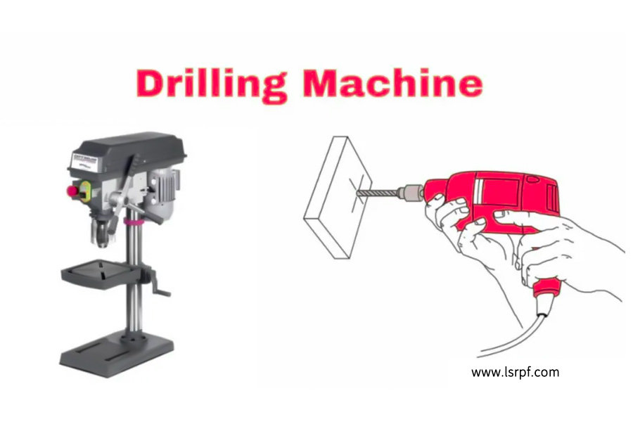
What is a drill machine?
A drilling machine is a heavy mechanical equipment used to drill holes underground. According to their uses, they can be divided into different types such as oil drilling machines, water well drilling machines, geological exploration drilling machines, etc. Despite the wide variety of types, the basic components of various drilling machines are similar, mainly including power system, lifting system, rotation system, circulation system, control system and well control system.
What are the main categories of drilling machines?
Drilling machines can be divided into the following categories according to application scenarios, functional characteristics and structural forms, and the core differences and typical applications of each type are as follows:
1.Hand-held drilling machine
- Features: Electric/pneumatic drive, weight <5kg, adjustable speed (usually 500-3000rpm)
- Typical applications: building installation, furniture assembly (equipped with quick-change chucks to adapt to different drill bits)
2.Bench Drill
- Core parameters: drilling diameter ≤ 16mm, spindle stroke 50-150mm
- Features: Cast iron body with depth ruler and angle adjustment
- Processing scene: batch processing of electronic product shells and small hardware
3.Upright Drill
- Specification range: spindle power 1.5-10kW, maximum drilling diameter up to 80mm
- Structural features: the height of the column can reach 2m, and the workbench is equipped with a T-slot clamp system
- Applicable objects: engine housing, hydraulic valve block and other medium-sized workpieces
4.Radial Drill
- Core advantages: cantilever extension range of 1-3m, headstock 360° rotation
- Typical configuration: hydraulic locking mechanism, centralized lubrication system
- Applications: processing of wind power flanges and large tubular plate components
- Technical features: positioning accuracy±0.01mm, equipped with ATC tool magazine (capacity 12-24)
- Advanced features: online measurement compensation, peck cycle programming
- Typical applications: aerospace composite components, PCB high-density hole groups
6.Multi-spindle
- Configuration: adjustable headstock (4-24 axes), each axis is fed independently
- Efficiency comparison: 300%-800% higher efficiency than single-axis
- Applicable industries: mass production of auto parts (such as brake drums, cylinder heads).
7.BTA Drill
- Special structure: high-pressure cooling system (7-20MPa), guide bushing device
- Machining capacity: depth-diameter ratio up to 100:1 (e.g. barrel drilling)
- Technical variants: different chip removal methods such as gun drills and spray suction drills
8.Magnetic Drill
- Key technology: permanent magnet suction≥20kN, power-off protection device
- Safety standard: IP54 protection level, automatic retraction of overload
- Usage scenario: on-site operation of ship deck and steel structure bridge
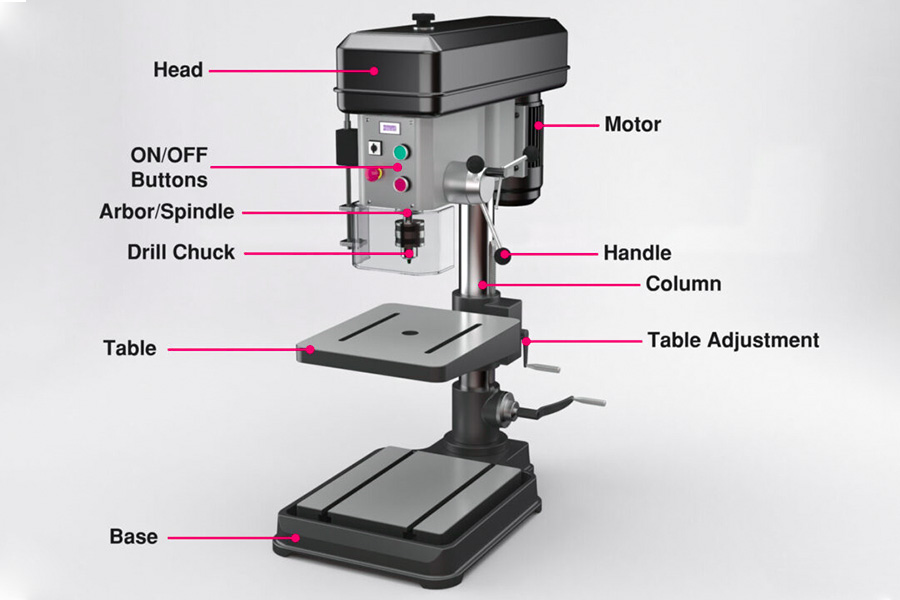
What are the parts of a drill machine?
The main components of the drilling machine are:
1. Power system
The power system is the core of the drilling machine, which is responsible for providing rotational and feed power, mainly including:
Electric Motors (AC/DC Motors): Provide spindle rotation power ranging from a few hundred watts (handheld) to tens of kilowatts (industrial drilling machines).
Transmission mechanism (belt, gear, direct drive):
- Belt drive: Commonly found in bench drilling machines, the speed is changed by adjusting the pulley.
- Gear drive: for heavy-duty drilling machines to provide more torque.
- Direct drive motor (CNC drilling machine): high precision, low vibration, suitable for CNC machining.
Pneumatic/hydraulic system (partial drilling machine): for feed control and clamp locking.
2. Spindle system
The spindle is a key component of the direct drive drill bit, which consists of:
- Headstock: Supports the spindle and ensures its stable rotation.
- Spindle bearings (rolling/hydrostatic): Affects rotational accuracy and life.
- Chuck systems (e.g. ER chucks, Morse taper sleeves): for fixing drill bits of different sizes.
- Cooling system (deep hole drilling machine): Cutting fluid is delivered through the internal coolant channel to reduce the temperature of the drill bit.
3. Feed system
Control the feed movement of the drill bit, which affects the machining accuracy and efficiency:
Manual feed (hand-held drill, simple drilling machine): Depends on the operator's manual control.
Automatic feed (CNC drilling machine, deep hole drilling):
- Servo motor ball screw (high-precision CNC drilling machine).
- Hydraulic feed (heavy duty drilling machine, providing stable pressure).
- Depth control device (limit block, digital ruler): to ensure that the drilling depth is consistent.
4. Rack and workbench
- Frame (column/bed): Provides structural rigidity and is typically made of cast iron or welded steel construction.
- Worktable: used to fix the workpiece, can be equipped with T-slot, vise or vacuum adsorption.
- Angle adjustment mechanism (radial drilling machine): allows the drill bit to be adjusted at multiple angles.
5. Control system
Conventional mechanical control (speed knob, clutch).
Numerical Control System (CNC):
- PLC or CNC system (such as Fanuc, Siemens) is adopted.
- Support G-code programming to achieve automatic processing.
- Safety control (overload protection, emergency stop).
6. Assistance systems
- Cooling lubrication system: reduces friction and extends drill bit life.
- Chip evacuation system (deep hole drilling machine): Chips are removed by means of high-pressure cutting fluid or screw chip conveyor.
- Dust collection device (woodworking drilling machine): prevents dust accumulation.
What are the structural differences between different types of drilling machines?
1. Handheld Drill vs. Benchtop Drill Press
| Components | Handheld Drill Press | Benchtop Drill Press |
|---|---|---|
| Power System | Small Motor (Battery/Power Supply) | AC Motor + Multi-speed Variable |
| Spindle System | Simple Chuck (Key/Self-tightening) | Morse Taper or ER Chuck |
| Feed System | Manual Press | Manual/Automatic Feed Lever |
| Frame | No Fixed Frame | Cast Iron Base + Column |
2. CNC drilling machine vs. traditional drilling machine
| Components | Traditional drilling machine | CNC drilling machine (CNC) |
|---|---|---|
| Power system | Fixed speed motor | Servo motor + frequency conversion control |
| Feed system | Manual/mechanical automatic | Ball screw + closed loop control |
| Control system | Mechanical speed regulation | CNC system + human-machine interface |
| Accuracy | ±0.1mm | ±0.01mm or higher |
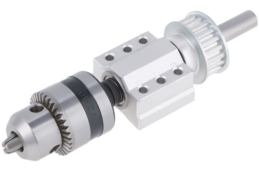
What is the Critical Role of Spindle Assembly in Precision Drilling?
In the field of precision machining, the spindle assembly is one of the most core components of the drilling machine, and its performance directly determines the accuracy, efficiency and quality of drilling. A high-quality spindle assembly can ensure that the drill bit maintains extremely high stability when rotating at high speed, thereby achieving micron-level machining accuracy.
The five key roles of the spindle assembly
1. Provide an accurate reference of the center of rotation
The spindle assembly provides a stable center of rotation for the drill bit through a high-precision bearing system and a rigid structure. According to the measured data of an auto parts factory in Hangzhou, when they upgraded the traditional bearings to ceramic bearings, the radial runout of the spindle was significantly reduced from the original 0.02mm to 0.005mm, and the machining accuracy was increased by 75%. This improvement in accuracy is directly reflected in the positioning accuracy of the hole position and the consistency of the hole diameter.
2. Deliver enough torque and power
The spindle made of SCM440 alloy steel (HRC58-62) has excellent strength and wear resistance, and is able to stably transmit the torque and power required for drilling. This material complies with JIS G4053 and has undergone a special heat treatment process to achieve a hardness of 58-62 degrees on the Rockwell to ensure dimensional stability under long-term high-load work.
3. Ensure the accuracy of tool installation
The MT3 Morse taper (ISO 296 accuracy ±0.005mm) is designed for more precise and reliable tool installation. This standardized taper interface enables fast tool changes while ensuring repeatable positioning accuracy after each tool change, making it ideal for precision machining where frequent drill changes are required.
4. Maintain the stability of high-speed rotation
The high-quality spindle assembly is designed with precision dynamic balancing and high-quality bearing support to minimize vibration, even at high rotational speeds. Good rotational stability not only improves machining accuracy, but also prolongs tool life and reduces machining costs.
5. Ensure long-term reliability
The well-designed spindle assembly has excellent heat dissipation and lubrication system to withstand the rigors of long-term continuous operation. Reasonable structural design and material selection greatly reduce the risk of thermal deformation and ensure the long-term stability of the processing dimension.
How Does Base Structure Determine Drilling Stability?
1. Basement structure: the first line of defense for stable drilling
The basement structure of drilling equipment is the foundation of the entire mechanical system, and its performance directly affects the drilling accuracy, equipment life and operation safety. The high-quality substrate design reduces vibration amplitude by more than 60% while improving drilling position accuracy by up to 50%.
1.1 The core function of the substrate structure
- Load support: Withstand static and dynamic loads when the rig is working
- Vibration Suppression: Absorbs and disperses cutting vibration energy
- Accuracy assurance: Provide a stable reference plane for the entire equipment
- Thermal stability: Resists deformation caused by changes in ambient temperature
2. The key to choosing substrate materials
2.1 Technical advantages of gray cast iron (GB/T 9439 HT250).
Material Parameters:
- The tensile strength ≥ 250MPa
- Hardness 180-240HB
- The damping coefficient is 3-5 times that of steel
Microscopic properties:
- The graphite sheet structure effectively absorbs vibrational energy
- The eutectic structure provides good thermal stability
Engineering Validation:
- Dongguan mold factory test shows that compared with welded steel structure, gray cast iron substrate vibration is reduced by 42%
2.2 Engineering Considerations for Weight Design
- Scientific basis for the 80kg benchmark value:
- The mass moment of inertia matches the common drilling force
- Ensure that the static stability factor ≥ 3.5
- Avoid resonant frequencies falling into the operating frequency band (typically 30-150Hz)
3. Analysis of the design of innovative shock absorption system
3.1 Mechanical optimization of honeycomb stiffeners
Structural parameters:
- The thickness of the ribs is 12-15mm
- Honeycomb unit size 80-120mm
- The height/thickness ratio is controlled at 5:1
Dynamic Performance:
- Increase natural frequency by 15-20%
- Increase structural stiffness by 30%
- Increases the effect of dispersing vibration energy by 40%
3.2 Technical characteristics of EPDM shock absorbing pads (ASTM D2000 M4BG 705).
Material Properties:
- Shore 70±5
- Compression set≤15%
- The dynamic damping coefficient is 0.15-0.25
Installation Scheme:
- Four-point symmetrical arrangement
- Pre-compression 10-15%
- The contact pressure is 0.8-1.2MPa
4. Project measurement data analysis
4.1 Comparative test of Dongguan Mould Factory (thick plate drilling condition)
| Parameters | Traditional structure | Optimized structure | Improvement rate |
|---|---|---|---|
| Vertical amplitude | 0.15mm | 0.05mm | 67% |
| Hole position deviation | ±0.08mm | ±0.03mm | 62% |
| Surface roughness | Ra3.2 | Ra1.6 | 50% |
| Drill life | 200 holes | 350 holes | 75% |
4.2 Vibration spectrum analysis results
- 50Hz main frequency vibration energy reduced by 72%
- High frequency harmonics (>200Hz) reduced by 85%
- Resonance peak elimination effect is significant
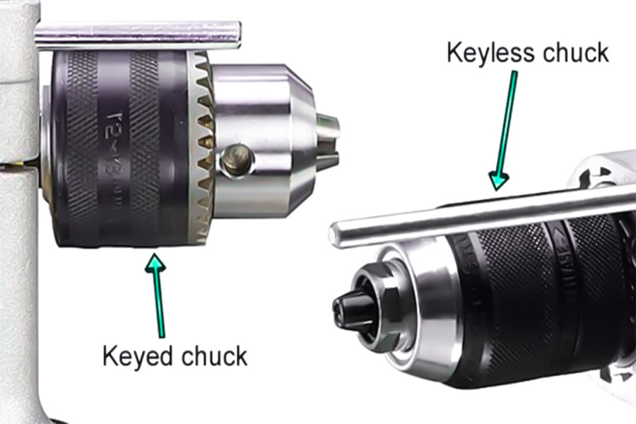
What Makes Drill Chuck the Core of Tool Holding System?
The drill chuck becomes the heart of the tool clamping system, based on six key benefits:
1.High-precision positioning
- Precision taper fit (e.g. JT33 taper)
- Radial run-out ≤ 0.01 mm (up to 0.003 mm for high-end models)
- Make sure that the tool is aligned with the spindle center of rotation
2.Quick tool change mechanism
- Three-jaw self-centering structure (120° uniform distribution)
- One-button quick-change design (tool change time< 10 seconds)
- No auxiliary tools are required to clamp/loosen
3.Broad compatibility
- Suitable for diameters from 1 to 13 mm (variable diameter design)
- Support all kinds of tools with straight shank/taper shank
- The through-hole construction is compatible with long rod tools
4.Superior rigidity
- High-quality alloy steel material (hardness HRC58-62)
- Spiral groove enhanced clamping force (≥100N·m)
- Seismic performance improves the quality of the machined surface
5.Safe and reliable
- Overload protection design (slipper clutch)
- Anti-loosening mechanism (double locking mechanism)
- More than 100,000 times fatigue life test
6.Ergonomic optimization
Anti-skid surface treatment
- Meets ISO10889 standards
- Visual indication of the clamping status
Typical application data show that the use of high-quality drill chucks can reduce tool deflection by 70%, increase machining efficiency by 25%, and extend tool life by 40%. This combination of precision, efficiency and reliability makes it an irreplaceable core clamping solution for modern drilling equipment.
How to Select Column Diameter for Heavy-Duty Operations?
A key consideration in the selection of column diameter
1. Load calculation is the foundation
- Static load: including the weight of the machine and the weight of the workpiece
- Dynamic load: consider the shock load factor (usually 1.2-1.5)
- Bending moment calculation: according to the cantilever length and the distance of the stress point
Calculation formula:
Column diameter D ≥ ³√ (32×M/(π×σ))
where M is the maximum bending moment, and σ is the allowable stress of the material
2. Material properties determine strength
Commonly used materials:
- Q345B Structural Steel (σs=345MPa)
- 40Cr alloy steel (quenched and tempered σb≥980MPa)
- Gray Cast Iron HT250 (suitable for scenarios with high vibration absorption requirements)
Safety:
- Generally take 2.5-3
- Recommendations 3-4 are recommended for heavy load conditions
3. The stability check cannot be ignored
- Slenderness ratio control: λ≤120 (λ≤80 in important occasions)
- Critical load calculation: Euler's formula check
- Local stability: wall thickness ≥ 1/20 of diameter
Recommended table of column diameters for heavy-duty operations
| Load level | Typical application | Recommended diameter (mm) | Wall thickness (mm) |
|---|---|---|---|
| 5-10 tons | Medium-sized drilling machines | 150-200 | 12-15 |
| 10-20 tons | Large milling machines | 200-250 | 15-20 |
| 20-30 tons | Heavy-duty boring machines | 250-300 | 20-25 |
| Above 30 tons | Mining machinery | 300-400 | 25-35 |
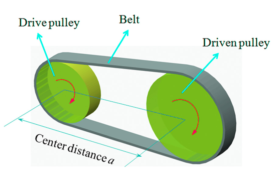
How Does Belt Drive System Impact Machining Efficiency?
1. Transmission efficiency directly affects energy consumption performance
Efficiency comparison data:
- Flat belt: 95-98% transmission efficiency
- V-belt: 92-96% transmission efficiency
- Synchronous belt: more than 98% transmission efficiency
Energy consumption difference:
- Inefficient transmission system may increase power consumption by 15-20%
- High-quality synchronous belt saves 8-12% energy compared to ordinary V-belt
2. Speed stability determines processing accuracy
Measured data:
- Multi-V belt speed fluctuation ≤0.5%
- Poor quality belt speed fluctuation can reach ±2%
Processing quality impact:
- Surface roughness Ra value fluctuation up to 30%
- Dimensional tolerance may deviate by 0.02-0.05mm
- Tool life shortened by 15-25%
Key performance indicator comparison table
| Parameters | Ordinary V-belt | High-quality synchronous belt | Improved effect |
|---|---|---|---|
| Transmission efficiency | 93% | 98% | +5% |
| Speed fluctuation | ±1.5% | ±0.3% | -80% |
| Service life | 2000h | 5000h | +150% |
| Maintenance cycle | 3 months | 6 months | +100% |
| Energy consumption performance | Baseline | 12% reduction | Significant improvement |
Summary
As the core equipment of precision machining, the performance of drilling machine depends on the high coordination of various components - the power system (motor/transmission mechanism) provides stable power, the spindle assembly (alloy steel spindle/precision bearing) ensures the rotation accuracy, the feed system (ball screw/servo drive) controls the processing depth, the rigid frame (cast iron base/reinforcement ribs) absorbs vibration, and auxiliary systems such as cooling, lubrication, and safety protection jointly guarantee the processing quality.
Reasonable selection of high-quality components such as SCM440 alloy steel spindle (hardness HRC58-62), gray cast iron body (HT250), and regular maintenance can improve the processing efficiency by more than 30% and extend the life of the equipment. It is recommended that users choose modular combination solutions according to processing requirements (precision/load/batch), and pay attention to the development trends of intelligent (Internet of Things monitoring) and green (energy-saving design) technologies to maintain competitiveness.

Disclaimer
The content of this page is for informational purposes only.LS SeriesNo representations or warranties of any kind, express or implied, are made as to the accuracy,completeness or validity of the information. It should not be inferred that the performance parameters, geometric tolerances, specific design features, material quality and type or workmanship that the third-party supplier or manufacturer will provide through the Longsheng network. This is the responsibility of the buyerAsk for a quote for partsto determine the specific requirements for these parts.please Contact us Learn more information.
LS Team
LS is an industry-leading companyFocus on custom manufacturing solutions. With over 20 years of experience serving more than 5,000 customers, we focus on high precisionCNC machining,Sheet metal fabrication,3D printing,Injection molding,metal stamping,and other one-stop manufacturing services.
Our factory is equipped with more than 100 state-of-the-art 5-axis machining centers and is ISO 9001:2015 certified. We provide fast,efficient and high-quality manufacturing solutions to customers in more than 150 countries around the world. Whether it's low-volume production or mass customization,we can meet your needs with the fastest delivery within 24 hours. chooseLS TechnologyIt means choosing efficiency, quality and professionalism.
To learn more, please visit our website:www.lsrpf.com
FAQs
1. What are the components of the drilling machine?
The drilling machine is mainly composed of eight core components: power system (motor, gearbox), spindle assembly (spindle, bearing, drill chuck), feed mechanism (handwheel, automatic feed device), column/frame (cast iron base, guide column), workbench (adjustable platform, T-slot), cooling system (pump, pipeline), protection device (shield, emergency stop) and control system (switch, governor).
2. What are the basic components of a drilling machine?
The most basic components of a drilling machine are the three core components: the power unit (which provides rotational power), the spindle system (which carries and transmits torque to the drill bit) and the support structure (columns/frames for stability), which determine the basic machining capacity of the machine and around which the other functional components are extended.
3. What are the eight parts of an electric drill?
A typical electric drill includes: (1) electric motor (core power) (2) gearbox (variable speed) (3) spindle (output shaft) (4) drill chuck (clamping tool) (5) housing (insulation protection) (6) switch/speed control trigger (7) power cord/battery (8) heat dissipation structure, and the portable design also contains safety components such as clutches.
4. How many parts does a drill have?
The standard twist drill bit is a single structure (1 part), but it can be disassembled into three functional parts: cutting part (main/auxiliary cutting edge), guide part (spiral groove, edge) and shank part (straight shank/taper shank); Combination drills (e.g. exchangeable drill bits) are usually composed of 2-3 parts (cutter heads, connecting rods, locking sleeves).