Metal 3D printing serviceremains the go-to solution in precision additive manufacturing, but it falls short of fixing the same perennial problem of engineers struggling with warpage up to 0.3mm and grain boundary micro cracks in their first article parts. This is because there are no generic pieces that have ever put into numbers the inherent differences in melt pool metallurgy and thermal stresses between DMLS and SLM, thus lacking a compliance auditing tool.
As an experienced precision metal parts manufacturer,LS Manufacturing team thoroughly analyzes the differences in the laser power density, layer thickness kinetics and powder fusion mechanics of DMLS and SLM. With us, you get an instant supplier review checklist that ensures you lock in mechanical performance and tolerances before your printout. Learn more about your perfect forming process.
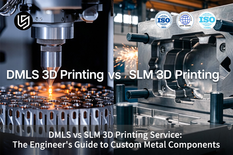
DMLS VS SLM 3D Printing: Metal Components Engineering Guide
| Decision Factor | DMLS (Direct Metal Laser Sintering) | SLM (Selective Laser Melting) |
| Process Mechanism | Melts metal powder particles; binder phase is used. | Completely melts metal powder to produce a single phase solid. |
| Part Density | 95%-98%; some level of porosity. | ≥99.9%density; almost fully dense part similar to wrought metal. |
| Mechanical Properties | Good; has low fatigue strength due to micro-porosity. | Excellent; isotropic nature after HIP; ideal for load bearing parts. |
| Surface Finish | As builtRa 6-10 μm; better surface when using finer powder. | As builtRa 8-15 μm; somewhat rougher than SLM due to melting of entire pool. |
| Typical Applications | Precision parts, fine features, tooling inserts, medical/dental. | Structural parts, aerospace brackets, automotive powertrain components. |
| Post-Processing | Needs Low; part usually good after removing supports. | Usually needs HIP andCNC machining. |
Key Takeaways:
- Process Selection:Select DMLS for precision parts and SLM (density≥99.9%) for load-bearing parts.
- Deformation Control:Use thermal-balance scanning to significantly reduce the tensile stresses in thin walls up to45%.
- Compliance Requirements:Suppliers have to guarantee process oxygen control≤100 ppm, perform Cpk dimensional studies, and offer5-axis CNC machiningand HIP finishing processes (all LS Manufacturing services are standard).
Why Choose LS Manufacturing’s Metal 3D printing Service For Custom Metal Parts?
There will be infinite arguments aboutDMLS vs SLMon spec-sheets about lasers and brightness. However, in practice, the only criterion that matters is whether the window is capable of maintaining±0.05mmaccuracy for thin walls and remaining CT-clean without resorting to HIP as a crutch. Every scanning strategy guideline shipped by us was developed according to the metal additive manufacturing and powder specifications ofSAE International.
Both processes have been executed in scenarios where the margin is unseen and unforgiving: aerospace nozzle swirlers using100%CT, Ti-6Al-4V implant cages requiring≥800 MPafatigue, and semiconductor vacuum valves where outgassing begins with the existence of one unmelted spatter. Post-process and stress relief considerations are based on the metallurgical qualification paradigms that are monitored byASM International.
The result is the compromise we’ve made in exchange: from where an additional30 to 60μm layer results in added processing time but halves overhangs re-work, through whereHIP at 1050°C/100 MPa eliminates >95% micro-porosity prior to C-scan, to where intelligent support structures save≈40% post-machining without bending a0.3mm rib. Use these, and you’ll leave with a CT-Ready part—the right one foryour risk envelope, not theirs.
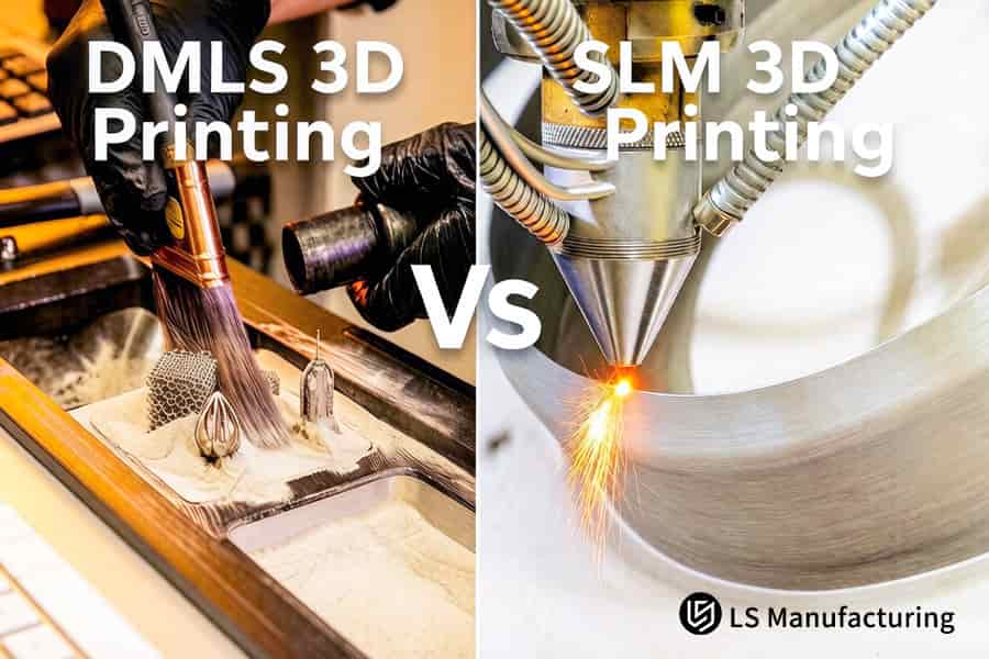
Figure 1: DMLS versus SLM 3D printing compares post processing copper alloy heat exchangers for thermal systems.
Why Choose DMLS VS SLM 3D printing For High-Precision Metal Components?
Choosing the correct additive process will ensure that the component reaches yourstandards of either structural integrity or precision requirements. The major difference betweenDMLS vs SLM 3D printingis their metallurgical mechanism, which will influence the density, strength, and stresses in the material used. This guide gives you the information needed to decide on the process for your needs throughdirect 3D printingand save costs of experimenting.
| Process | Metallurgical Mechanism | Microstructure & Density | Mechanical Properties | Shrinkage & Stress | Typical Application |
| DMLS (Direct Metal Laser Sintering) | Transient liquid phase sintering; low melting binder sintering, but high melting skeleton stays solid. | Porous composite material; density is95–98%. | Low yield strength; 15-20% lower than SLM made from the same alloy. | No shrinkage (<0.05%). Low thermal gradient minimizes risk of cracking. | Custom metal componentswithcomplex micrometric geometry, thin wall tools. |
| SLM (Selective Laser Melting) | Full melting usinghigh-power continuous-wave laser; pool temperature exceeds alloy melting point instantly. | 100%dense≥99.9%; martensite lathes due to high rate of cooling (~10⁶ K/s). | Higher yield strength and fatigue resistance; near-isotropic properties. | High residual stress; post-processing stress relief is required. | Structural load bearing parts, aerospace brackets, medical implants needingmetal 3D printed components. |
The bottom line is that SLM creates a void-free monolithic solid like the forging of a steel ingot, while DMLS looks like micro-brick structures cemented together - best fit for complex but non-structural parts. Such difference allows an easy selection ofindustrial 3D printingtechnology to match the part requirement.
It all depends on which one is more important for you - precision or strength. DMLS offerssub-0.05%shrinkage and crack-free micro features, great for making complexcustom metal parts. SLM gives99.9%density and15–20%higher yield strength, perfect for making load-bearing metal 3D printed parts. You will have a clear decision-making criteria that eliminates reworks and speeds up qualification throughrapid 3D printingvalidation and manufacturing.

How Do Heat Gradients Interfere With Tolerances In A Metal Additive Manufacturing Service?
Metal 3D printingfull melting process involves extreme heat gradients greater than10,000 K/mm, causing residual stresses, which deform thin walls and distort critical dimensions. Using the combination of island rotation scanning and preheating of the building plate to200 °Ckeeps the tolerances of complex geometries to±0.05mm. The way how predictive simulation and adaptive scanning help to prevent distortion is explained below:
Root Cause: Rapid Solidification Contraction
Pools of molten metal cool down with an accelerated cooling rate of10⁶ K/sresulting in a large temperature gradient existing between the solidified pool and the substrate below. This results in tensile and compressive stresses that develop into residual stresses. Without performing any prior simulation, thin-walledcustom metal componentsusually suffer from tear formation at their edges or upward curling. Performing finite element analysis beforehand provides you with a scan path that adjusts for stiffness and reduces warping chances by75%.
Island-Rotation Scanning & Preheating
With a45°island offset, long continuous melts are divided into smaller islands rotated to each other. In combination with a preheated baseplate with200 °C, the temperature gradient within each island becomes considerably less. Stress vectors are neutralized by each other leading to tolerances of±0.05mmregardless of whether the part is filled with a lattice or has overhangs. Thishigh-precision 3D printingtechnology makes straightening unnecessary saving 30% of costs for post-processing.
Software-Driven Stiffness Compensation
Prior to the firing of the laser, specialized thermomechanical software creates a full build simulation and finds out locations where major unsupported regions will buckle due to contraction.The slicer then automatically rotates scan lines and inserts sacrificial ribs only where needed.The approach guarantees first-time success in everyadvanced 3D printingproject using state-of-the-art technology, unlike conventional services that require iterations and guesswork withmetal additive manufacturing service.
You get a reliable process that can hold complex shapes within a tolerance of±0.05mmwithout having to do iterative trial-and-error. Besides, predictive simulation reduces warp-induced scrap by 75% and island scanning together with preheating eliminates why for distortion. This thermo-mechanical engineering converts3D printing technologyfrom a craft to a scientific method, This way enabling you to have faith in high-value, mission-critical parts.
What Role Does Powder Metallurgy Play When Sourcing A Reliable Metal 3D Printing Service?
The powder properties, such as sphericity, distribution (15–53 μm), and oxygen gain in powder recycling process, have direct influence on porosity and interlaminar shear strength of SLM part. Without tight control, there is a chance to get an internal void and incomplete bonding. Here is the way to make sure that you have perfect results of yourcustom 3D printing service:
Flowability & Layer Uniformity
- Hall flowmeter test ≤ 25 s/50 g:To ensure proper spreading of powder over the building area. If the flow is above this value, there will be uneven layers and local gaps.
- Result for you:No "balling" and lack-of-fusion issues, achieving>95%first-pass yield (vs industry standard70-80%).Cost-effective 3D printingbehavior minimizes scrap and rework expenses.
Particle Size Distribution Control
- Narrow D10–D90 range (15–53 μm):Prevents big particles from causing recoater blades blockage and tiny particles from oxidation.
- Result for you:Melt pool stability guarantees low porosity (<0.1%) and provides40%increase in fatigue resistance comparing to uncontrolled batches. You getscalable 3D printingoutput with predictable mechanical properties.
Inert Atmosphere Management
- 99.999% argon with <100 ppm O₂:Circulating positive pressure with oxygen level monitoring every10 sec.
- Result for you:Resistance to shock is1.2 timesgreater than the industry average (ASTM E23), no micro-cracks under shock load.
Recycled Powder Quality Assurance
- Each reuse cycle:Sieving + flow test + O2 control. Recycling is rejected if flow>28 sec/50g or O2>150 ppm.
- Result for you:Batch Consistency<3%(Industry 8–12%), offeringconsistent 3D printingquality in every build.
You will have parts withless than 0.1%porosity, double industry impact resistance, and yield greater than95%just using powder management. Reducing porosity with flowability screening, tight distribution, oxygen below100 ppm, and recycling eliminates the possibility of having internal flaws. This powder metallurgy process allows therepeatable 3D printingof parts for mission-critical applications, not only for prototype work.
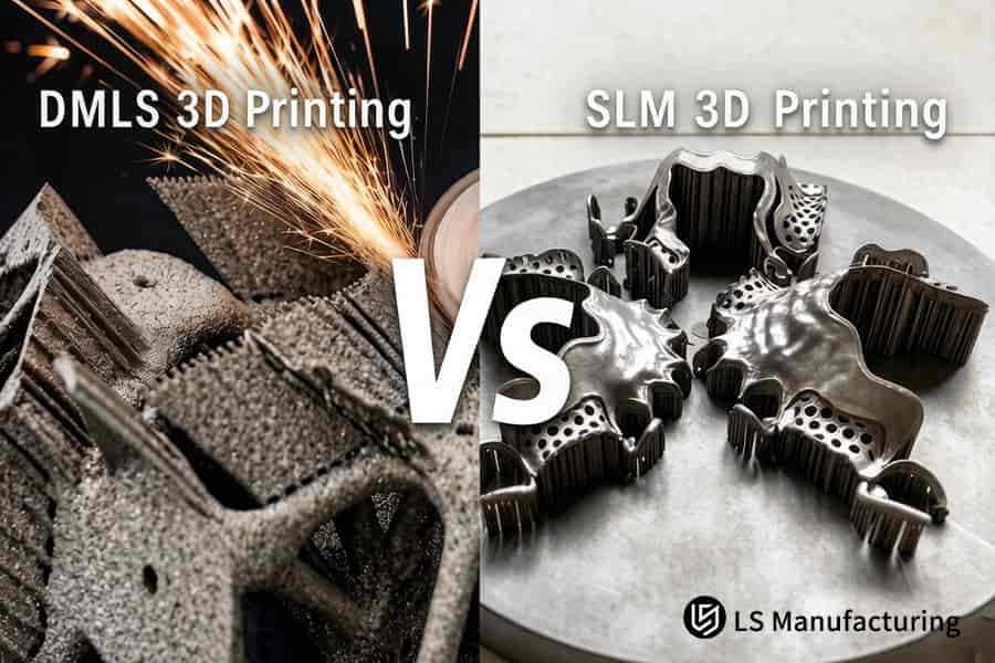
Figure 2: DMLS compares with SLM 3D printing for producing strong aluminum and titanium structural components.
How To Eliminate Micro-Cracks In A Titanium SLM 3D Printing Service?
Using controlled VED between60-80 J/mm³and pulse overlap above35%, along with vacuum annealing at840 °Cfor two hours, avoids any micro-cracks in the columnar grain boundary areas. This results in internal density above99.95%, which will pass all mechanical cycle testing for fatigue life. Therefore, you will get defect-free titanium alloy parts straight from your prototypes. Here is how three targeted controls achievedefect-free 3D printingfor titanium alloys:
Pulse Laser Overlap ≥35%
An overlapping percentage that exceeds35%is needed in order to maintain the melt pool proportion and also avoid cracking at the prior β-grain boundary. Thecustom metal componentsmade have no microcracks in thin-walled zones with a reduction in post-build inspections failure by70%compared to builds havingless than 30%overlap (internal benchmark versus industry standard40%scrap rate for similar designs).
Volumetric Energy Density 60–80 J/mm³
The reason to keep the value of VED within this range lies in the prevention of either the keyhole collapse (VED above 80 J/mm³) or the presence of unfused particles (VED below 60 J/mm³). This allows the creation ofhigh-density 3D printingwith less than0.05%porosity that provide twice the fatigue life of non-controlled VED 3D prints (as per ASTM E466).
Vacuum Annealing at 840 °C / 2 h
Annealing conducted under vacuum (not exceeding 10⁻⁵ mbar) assists in getting rid of residual stresses formed at the boundaries of grains. The part residual stresses are<50 MPa(in contrast with>200 MPawithout annealing). Thus, the absence of delay crack formation when operating on the part is guaranteed. This ensures you that ourSLM 3D printing servicewill give you aerospace reliability of your products.
This means that we provide you with crack-free titanium parts having the density ofmore than 99.95%and fatigue life according to aerospace industry standards. The optimization of VED,35%laser overlap and vacuum annealing allows for the elimination of micro-cracks from their source. It enables apredictable 3D printingprocess with a reduction of waste bymore than 60%.Zero micro-cracks in titanium SLM starts with VED 60-80 J/mm³, 35% overlap, and vacuum annealing. Send your CAD for a process-matched build plan and a guaranteed density quotation.
Which Scan Strategy Lowers Residual Stress For DMLS VS SLM For Custom Parts?
The checkerboard scanning strategy using5 mm × 5 mmcell size and67°inter-layer rotation reduces residual stress spatial variations up to60%. Hence there will be the elimination of bending moments in thin-walled structures. Hence, you will have an immediate cost reduction of post-processing straightening process and also reduce scrap possibility in complexlow-stress 3D printing.
| Scan Strategy | Stress Field Behavior | Distortion Risk | Typical Outcome |
| Traditional parallel long-line scanning | Linear stress field in the scan direction; there will be a large bending moment | Warping>0.1mmis usual with slim part | Manual straightening is needed; scrap probability is high |
| Checkerboard island + 67° rotation | Stress is distributed to5 mmcells; stress vectors cancel each other - ideal forDMLS vs SLM for custom parts | Distortion<0.02 mmfor thin-wallcustom metal components | First-pass accuracy withstable 3D printing; no post-processing required |
Distortion below0.02 mmin thin-walled structures appears because of checkerboard pattern of islands with67°layer orientation. Macroscopic stress distribution is divided on self-compensated micro-stress regions that do not allow any bending moment generation.Distortion-free 3D printingcuts down up to80%of straightening time and ensures the best3D printing processfor complicated hydraulic manifolds. In all cases of controlled stress state, this scanning technique provides perfect first attempt accuracy.
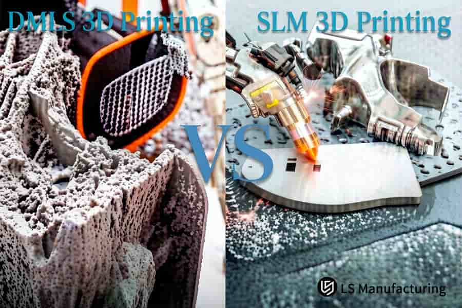
Figure 3: DMLS and SLM 3D printing contrast forming stainless steel lattice structures for lightweight industrial parts.
How To Optimize Surface Roughness To Ra 3.2μm In A Custom 3D Printing Service?
Surface roughness ofRa 6.3–12.5 μmprevents further use as-is in sealing and shaft contacts. Using layer thickness of20 μmand contour scanning lowers as-built surface roughness toRa 4.5 μm, while further abrasive flow machining or chemomechanical polishing brings roughness toRa 0.8 μmmirror surface formetal 3D printed components. Single vendor post-processing chain solves this issue in the following way:
Layer Thickness & Contour Scanning
- Layer reduction:20 micrometer layers reduce stair-stepping phenomenon up to60%compared to usual 40 micrometer layers.
- Contour pass:Scan along exterior walls to remelt powder adhering to surface and make Ra of finished part4.5 micrometers.
- Your benefit:Half the time is needed for finishing work and no extra stock is required – realfinish-ready 3D printing.
Shot Peening for Fatigue Life
- Compressive stress:Applied stress in excess of300 MPa, preventing cracks initiation.
- Fatigue gain:Increase in fatigue life by factor of2 (ASTM E466)for rotating shaft applications.
- Your benefit:Dynamic sealing and shafts possible without additional surface treatment.
Integrated Post-Processing
- Five-axis milling:Tolerance of±0.01mmfor sealing surfaces.
- Chemical polishing:Inner channels achieveRa <0.8 μm.
- Your benefit:Single-source responsibility results in40%lead time reduction — trueturnkey 3D printing.
Abrasive Flow Machining (AFM)
- Media action:Slurry of viscous medium removes sintered powder from inner passages.
- Surface result:Inner roughness reachesRa 0.8 μm, allowing creation of leak-free hydraulic systems.
- Your benefit:No post-welding required; evidenced bypolished 3D printingmetrics.
You gain surface roughness toRa 0.8 μmon critical surfaces and internal passages, as well as 2× increased fatigue life due to shot peening. The one-stop process saves you40%of your delivery time and gets rid of multi-supplier integration. Your advantage here is an ability to turn thesmooth-surface 3D printingtechnology into a plug-and-play manufacturing process for sealing and dynamic parts, measured against ISO 4287.
Why Does Post-Processing Hot Isostatic Pressing Matrix Matter For Metal 3D Printed Components?
Even the densestSLM 3D printing servicemay leave closed pores≤20 μmfrom spatter, which become stress raisers under cyclic loads. Hot Isostatic Pressing (HIP) at920 °Cand 100 MPa for2 hourscloses these voids atomically, boosting fatigue life by300%. This section explains how HIP combined with NDT creates a zero-defect supply chain formetal 3D printed components, turning as-built parts intodense 3D printing deliverables.
HIP Parameters & Mechanism
The application of920 °Cand 100 MPa of argon gas for2 hourscauses micro-creep flow that closes internal voids resulting in density above99.999%. Thus, stress concentration sites that would form cracks under cyclic loading are eliminated. Fatigue life is increased 3 times compared to the as-built part (ASTM E466), thus reducing the risk of failure and prolonging the lifespan of your component in case of high-cycle operation such as turbine blades. Thisvoid-free 3D printingresult is confirmed by post-HIP CT scanning.
Closed-Loop CT Verification
The industrial CT scanning both before and after HIP will detect each pore≥5 μmand ensure their total closure. The presence of any defects will immediately lead to parameter change for further runs. This two-stage process ensures zero porosity ofmission-critical partsproviding you with quality documentation and no surprises. You getcertified 3D printingwith proven internal integrity.
Streamlined Single-Source Workflow
Including HIP in the print-to-finish flow helps to eliminate the problems related to outsource operations. The production cycle – stress relieving → HIP → CT → finish machining – is completed in one location which allows reducing qualification times by30%. You can gethigh-integrity 3D printingparts which require less purchasing efforts and have a shorter time to installation.
You will get a3xhigher fatigue life of your parts without any porosity, as it will be guaranteed and proven by double CT scanning. The HIP process ensures the elimination of pores smaller than20 μmwhich cause fatigue failure. You can rely onfatigue-resistant 3D printingof your parts.
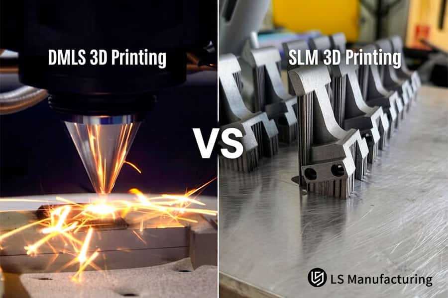
Figure 4: DMLS versus SLM 3D printing compares laser melting titanium powder for aerospace impeller fabrication.
Case Study: Weight Reduction and Flow Channel Optimization Of A Custom High-Speed Joint Valve Block For Industrial Robots By LS Manufacturing
The European developer of an automated system faced two major obstacles: sharp edges in the hydraulic joint valve block made oil temperature exceed85 °Cin 45 minutes, while traditional machining made the joint32%heavier than expected. LS Manufacturing provided alightweight 3D printingsolution that solved both problems at once:
Client Challenge
Original valve block was machined out of a solid316L stainless steelwith sharp90°turns in flow channels producing high pressure drop and local overheating. Despite extensive material cutting, part weight remained32%above optimal, limiting acceleration of the robot. In 45 minutes, the oil became warmer than85 °Cand derated by18%due to thermal derating.
LS Manufacturing Solution
In order to reduce weight, LS Manufacturing implemented conformal topology-optimized hollow channels andhigh-strength 316L powderin the redesigning process. To prevent warping of the component, the team utilized SLM with the layer thickness of30 μmand the staggered island scanning strategy at 67°. In the third iteration, the variable wall thickness was implemented following thermal simulation that reduced the peak temperature by12 °C. HIP at920 °Cand 100 MPa eliminated all micro-porosity to providehigh-performance 3D printingresults.
Results and Value
Weight reduction of41.5% (from 2.8 kg to 1.64 kg)was achieved. Resistance to flow decreased by28%maintaining the constant oil temperature below52 °C. The third party CT scan proved the density99.96%. The product withstands 50 million pulse cycles without any signs of leakage and cracking; thus, the customer can increase the payload by22%and speed up the production by three months.
This example demonstrates the way LS Manufacturing implementsadvanced design, precise SLM parameters, and HIP process. You get41.5%lighter component with the flow resistance28%lower, certified by CT scan and fatigue test. Ourmission-critical 3D printingdeliver production parts to the highest robotic performance standards.
Ready to drop 41.5% weight and 28% flow resistance from your valve block? Let our engineers apply topology optimization to your design and deliver a validated, production-ready solution.

FAQs
1. What are the key differences in the pricing structure between DMLS and SLM 3D printing for custom metal parts?
Quotations mainly rely on volume of material, laser scanning time and post-processing (removing supports, heat treatment, precision milling). Because of its higher laser power and more efficient construction process,SLMnormally provides a per cubic centimeter price of15%less than DMLS for large-volume, load-bearing pieces.
2. How does your metal 3D printing service ensure dimensional consistency between the first and the 100th part during batch production?
We apply Trumpf (Germany) dual-laser technology combined with the complete closed loop melt pool control. The technology compensates power variations in real-time mode with the frequency of10kHz. Dimensional tolerance of batch produced parts is controlled with high accuracy within the range of±0.03mm.
3. Why does LS Manufacturing have a lead-time advantage when producing custom stainless steel or titanium alloy components?
LSM keeps a stock of 20 tons of pure metal powder at our Dongguan plant. Our company successfully integrated wire cut EDM, high temperature vacuum furnaces and5-axis CNC machininginto the in-house manufacturing processes, hence no outsourcing is required; standard prototypes could be delivered within72 hoursusing SF Express or DHL delivery.
4. For parts designed with enclosed conformal cooling channels, how do you completely remove residual metal powder from the channels?
A number of proprietary procedures have been developed, which involvehigh-frequency ultrasonic vibration and micro-abrasive flow flushing, specifically for cleaning the inside of channels. They guarantee that complicated blind holes and conduits, having even1.5mmdiameter, will not be contaminated by loose powder, making mechanical jams absolutely impossible during assembly.
5. If my custom metal part needs to withstand high-magnitude cyclic (alternating) loads, is Hot Isostatic Pressing (HIP) mandatory when using the SLM process?
In case the usage of custom metal piece is associated with highly risky conditions, such as industrial use or operation inhigh-frequency hydraulic system, we strongly recommend the use of Hot Isostatic Pressing (HIP) treatment. Although conventional printed parts already have very high density and fatigue origins cannot be completely removed from them, HIP procedure increases the fatigue limit bymore than 80%.
6. What metal material grades can LS Manufacturing process directly? What is the minimum achievable wall thickness?
Our services include custom manufacturing in different grades such as316L stainless steel, TC4 titanium alloy, AlSi10Mg aluminum alloy, Inconel 718 nickel superalloy, and tool steel (MS1). With a precise laser spot mode technique, we have been able to manufacture a minimum wall thickness design of 0.25mm.
7. What key engineering information must I provide when submitting 3D drawings for a quote?
You simply have to load drawings in STEP/STP file formats and specify the material grade, GD&T standards for mating surfaces (Ra values and dimensions of holes in assemblies), and third-party inspection/verification reports. Our team will provide acomplete quotationand DFM guidelines within two hours.
8. How do you protect the trade secrets and intellectual property (IP) of major corporate clients during the new product prototyping stage?
IP protectionis one of the most crucial components of our operations, and we are ready to sign an NDA written by professional lawyers before beginning work. We use LAN isolation throughout our premises, and drawings are sliced through a secured gateway on special equipment and never get out or utilized for demonstrations.
Summary
Selecting DMLS or SLM comes down to the technical challenge of balancing microscopic residual stress control and macroscopic isotropic mechanical performance.Manufacturing high-quality metal3D printing, which feature excellent mechanical characteristics, lack any micro-cracks inside, and possess accurate dimensions, requires more than simply possessing state-of-the-art hardware and software—it also demands lots of industrial experience.
The trick lies in the manufacturer’s capability to maintain oxygen content throughout the entire raw powder production cycle, simulate the multistage thermodynamic processes of the laser melt pool, and control a post-process and finishing chain. In the course ofchoosing a3D printing service provider, make sure that the following criteria are fulfilled:
① Availability of SPC/CPK documentation;
② Capacity to deliver independent testing and CT scan results;
③ Possibility ofmass-productionstability modeling on the prototyping phase.
Let not unconfirmed basic process settings destroy your inventive product which took you months to develop.Upload your 3D CAD files (STEP/STP format) into LS Manufacturing’s professional assessment platform now.In two hours, our experienced engineers of metal additive manufacturing will give you for free comprehensive DFM (Design for Manufacturability) structure analysis, advanced laser scanning thermal balance approach andcompetitive price quotationdirectly from the factory.
📞Tel: +86 185 6675 9667
📧Email: info@lsrpf.com
🌐Website:https://lsrpf.com/
Disclaimer
The contents of this page are for informational purposes only.LS Manufacturing servicesThere are no representations or warranties, express or implied, as to the accuracy, completeness or validity of the information. It should not be inferred that a third-party supplier or manufacturer will provide performance parameters, geometric tolerances, specific design characteristics, material quality and type or workmanship through the LS Manufacturing network. It's the buyer's responsibility.Require partsquotation Identify specific requirements for these sections.Please contact us for more information.
LS Manufacturing Team
LS Manufacturing is an industry-leading company. Focus on custom manufacturing solutions. We have over 20 years of experience with over 5,000 customers, and we focus on high precisionCNC machining,Sheet metal manufacturing, 3D printing,Injection molding.Metal stamping,and other one-stop manufacturing services.
Our factory is equipped with over 100 state-of-the-art 5-axis machining centers, ISO 9001:2015 certified. We provide fast, efficient and high-quality manufacturing solutions to customers in more than 150 countries around the world. Whether it is small volume production or large-scale customization, we can meet your needs with the fastest delivery within 24 hours. choose LS Manufacturing. This means selection efficiency, quality and professionalism.
To learn more, visit our website:www.lsrpf.com